Position Synchronized Output (PSO)
The PSO signal is available on the dual-function AUX Marker/PSO signal lines.
Use the PSO pulse external sync functions to configure the auxiliary marker as an output.
Use the PsoOutputConfigureOutput() function to:
- transmit the PSO output signal on the Marker ± pins differentially
- configure the Marker - pin as a 5V TTL PSO output.
For more information, refer to Automation1 Help.
You cannot use a sine wave encoder with the -MX1 multiplier option as an input to the PSO. The -MX1 option does not generate emulated quadrature signals.
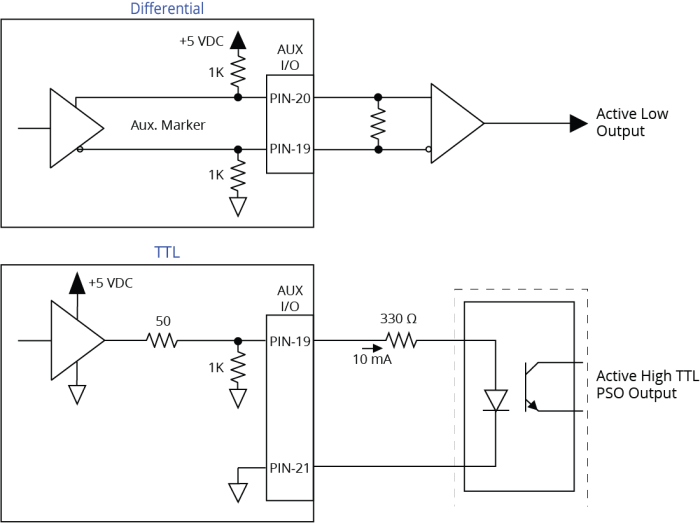
When configured for differential use with pin 19 as PSO Differential Output - and pin 20 as PSO Differential Output +, the PSO output is active low. PSO Interface shows how the output pins are biased so that the output is in the OFF state when it is not actively driven. If you want an active high output, you can change the pins so that pin 19 is the PSO Differential Output + and pin 20 is the PSO Differential Output -.
The differential signal format is recommended when using long cable lengths in noisy environments or when high frequency pulse transmission is required. It is best to locate the line receiver close to the receiving electronics. A 5 V TTL signal is used to drive an opto coupler or general purpose TTL input. This signal is active high and is driven to 5 V when a PSO fire event occurs. When the drive is reset or after initial power up, the PSO pins (refer to PSO Pins on the Auxiliary I/O Connector), are not actively driven and the fail safe state is defined by pull-up and pull-down resistors as shown in PSO Interface.
The -EB1 I/O option board has additional PSO signal formats. Refer to PSO Interface [-EB1] for more information.
Table 2-39: PSO Specifications
|
Specification |
Value |
|
|---|---|---|
|
Output |
TTL |
5 V, 16 mA (max) |
|
Maximum PSO Output (Fire) Frequency |
TTL |
12.5 MHz |
|
RS-422 |
12.5 MHz |
|
|
Output Latency [Fire event to output change] |
TTL |
25 ns |
|
RS-422 |
25 ns | |