Feedback Connector
The connector pin assignment is shown in Feedback Connector Pinout with detailed connection information in the following sections.
Table 2-13: Feedback Connector Pinout
|
Pin # |
Description |
In/Out/Bi |
Connector |
|---|---|---|---|
|
1 |
Reserved |
N/A |
|
|
2 |
Motor Over Temperature Thermistor |
Input |
|
|
3 |
+5V Power (1) |
Output |
|
|
4 |
Plug and Play Serial Data (for Aerotech stages only) |
Bidirectional |
|
|
5 |
Hall-Effect Sensor B (brushless motors only) |
Input |
|
|
6 |
Encoder Marker Reference Pulse - |
Input |
|
|
Absolute Encoder Clock - |
Output |
||
|
7 |
Encoder Marker Reference Pulse + |
Input |
|
|
Absolute Encoder Clock + |
Output |
||
|
8 |
Absolute Encoder Data - |
Bidirectional |
|
|
9 |
Reserved |
N/A |
|
|
10 |
Hall-Effect Sensor A (brushless motors only) |
Input |
|
|
11 |
Hall-Effect Sensor C (brushless motors only) |
Input |
|
|
12 |
Clockwise End of Travel Limit |
Input |
|
|
13 |
Brake Output - |
Output |
|
|
14 |
Encoder Cosine + |
Input |
|
|
15 |
Encoder Cosine - |
Input |
|
|
16 |
+5V Power (1) |
Output |
|
|
17 |
Encoder Sine + |
Input |
|
|
18 |
Encoder Sine - |
Input |
|
|
19 |
Absolute Encoder Data+ |
Bidirectional |
|
|
20 |
Signal Common |
Output | |
|
21 |
Signal Common |
Output | |
|
22 |
Home Switch Input |
Input |
|
|
23 |
Encoder Fault Input |
Input |
|
|
24 |
Counterclockwise End of Travel Limit |
Input |
|
|
25 |
Brake Output + |
Output |
|
|
(1) The maximum combined current output is 500 mA. |
|||
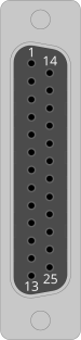
Table 2-14: Feedback Mating Connector Ratings
| Specification | 25-Pin Solder Cup |
Backshell |
|---|---|---|
| Aerotech Part Number | ECK00101 | ECK00656 |
| Amphenol Part Number (1) | DB25P064TXLF |
17E-1726-2 |
| Maximum Wire Size | 20 AWG (0.5 mm2) |
N/A |
|
(1) Refer to the manufacturer website for additional information. |
||