Digital Inputs [-EB1]
Input bits are arranged in groups of 4 and each group shares a common pin. This lets a group be connected to current sourcing or current sinking devices, based on the connection of the common pin in that group.
To be able to connect an input group to current sourcing devices, connect the input group's common pin to the power supply return (-). Refer to Digital Inputs Connected to Current Sourcing (PNP) Devices [-EB1].
To be able to connect an input group to current sinking devices, connect the input group's common pin to the power supply source (+). Refer to Digital Inputs Connected to Current Sinking (NPN) Devices [-EB1].
The digital inputs are not designed for high-voltage isolation applications. They should only be used with ground-referenced circuits.
Table 3-18: Digital Input Specifications [-EB1]
|
Input Voltage |
Approximate Input Current |
Turn On Time |
Turn Off Time |
|---|---|---|---|
|
+5 V to +24 V |
6 mA |
10 µs |
43 µs |
Table 3-19: Digital Input Connector Pinout [-EB1]
|
Pin# |
Description |
In/Out/Bi |
Connector |
|---|---|---|---|
|
1 |
Input Common for Inputs 0-3 |
Output |
|
|
2 |
Input 0 (Optically-Isolated) |
Input |
|
|
3 |
Input 1 (Optically-Isolated) |
Input |
|
|
4 |
Input 2 (Optically-Isolated) |
Input |
|
|
5 |
Input 3 (Optically-Isolated) |
Input |
|
|
6 |
Input Common for Inputs 4-7 |
Output |
|
|
7 |
Input 4 (Optically-Isolated) |
Input |
|
|
8 |
Input 5 (Optically-Isolated) |
Input |
|
|
9 |
Input 6 (Optically-Isolated) |
Input |
|
|
10 |
Input 7 (Optically-Isolated) |
Input |
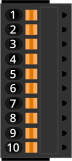
Table 3-20: Digital Input Mating Connector Ratings [-EB1]
| Specification | Description | |
|---|---|---|
| Type | 10-Pin Terminal Block | |
| Part Numbers | Aerotech: ECK02395 | |
| Phoenix: 1700841 | ||
|
Conductor Cross Section |
Solid or stranded | 20...26 AWG (0.14...0.5 mm2) |
| Stranded, with ferrule, without plastic sleeve | 20...24 AWG (0.25...0.5 mm2) | |
| Conductor Insulation Strip Length | 8 mm (5/16 in) | |
|
(1) Refer to the manufacturer website for additional information. |
||
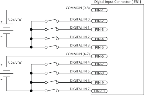
Figure 3-14: Digital Inputs Schematic [-EB1]

Each bank of four inputs must be connected in an all sourcing or all sinking configuration.
Figure 3-15: Digital Inputs Connected to Current Sourcing (PNP) Devices [-EB1]
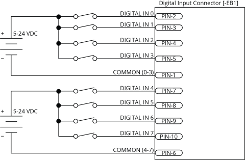
Figure 3-16: Digital Inputs Connected to Current Sinking (NPN) Devices [-EB1]