DC Brush/Voice Coil Motor Connections
The configuration shown in DC Brush/Voice Coil Motor Configuration is an example of a typical DC brush or Voice Coil motor connection. Refer to DC Brush/Voice Coil Motor Phasing for information on motor phasing.
Figure 2-8: DC Brush/Voice Coil Motor Configuration
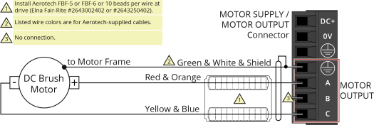
Table 2-9: Wire Colors for Aerotech-Supplied DC Brush/Voice Coil Motor Cables
|
Pin |
Wire Color Set 1(1) |
Wire Color Set 2 |
Wire Color Set 3 |
|---|---|---|---|

|
Green & White & Shield (2) |
Green/Yellow & Shield |
Green/Yellow & Shield |
|
A |
Red & Orange |
Red |
Red & Orange |
|
C |
Yellow & Blue |
Black |
Yellow & Blue |
|
(1) Wire Color Set #1 is the typical wire set used by Aerotech. (2) “&” (Red & Orange) indicates two wires; “ / ” (Green/White) indicates a single wire. |
|||