Digital Inputs
Input bits are arranged in a group of 4 and share a common pin (INCOM, PIN-7, located on the Auxiliary I/O connector). This lets a group be connected to current sourcing or current sinking devices, based on the connection of the common pin.
To be able to connect an input group to current sourcing devices, connect the common pin to the power supply return (-). Refer to Digital Inputs Connected to Current Sourcing (PNP) Devices .
To be able to connect an input group to current sinking devices, connect the common pin to the power supply source (+). Refer to Digital Inputs Connected to Current Sinking (NPN) Devices .
The digital inputs are not designed for high-voltage isolation applications. They should only be used with ground-referenced circuits.
Table 2-15: Digital Input Specifications
|
Input Voltage |
Approximate Input Current |
Turn On Time |
Turn Off Time |
|---|---|---|---|
|
+5 V to +24 V |
6 mA |
10 µs |
43 µs |
Table 2-16: Digital Input Pins on the I/O "B" Connector
|
Pin # |
Label |
Description |
In/Out/Bi |
|---|---|---|---|
|
1 |
DI0 |
Digital Input 0 (Optically-Isolated) |
Input |
|
2 |
DI1 |
Digital Input 1 (Optically-Isolated) |
Input |
|
3 |
DI2 |
Digital Input 2 (Optically-Isolated) |
Input |
|
4 |
DI3 |
Digital Input 3 (Optically-Isolated) |
Input |
Table 2-17: Digital Input Pin on the Auxiliary I/O Connector
|
Pin # |
Label |
Description |
In/Out/Bi |
|---|---|---|---|
|
7 |
INCOM |
Digital Input Common | Input |
Figure 2-5: Digital Inputs Schematic
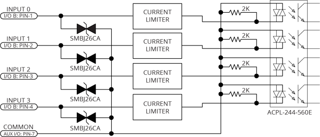
IMPORTANT: Each bank of four inputs must be connected in an all sourcing or all sinking configuration.
Figure 2-6: Digital Inputs Connected to Current Sourcing (PNP) Devices
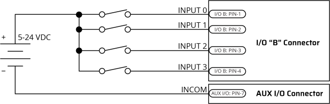
Figure 2-7: Digital Inputs Connected to Current Sinking (NPN) Devices