Position Synchronized Output Connector
Program the Position Synchronized Output (PSO) to generate an output that is synchronized to the feedback position of an axis. PSO is typically used to fire a laser or trigger an external hardware device. The XL4s supports three-axis PSO in Automation1 versions 2.4.0+. The XL4s supports dual-axis PSO in A3200 and Automation1 versions before 2.4.0.
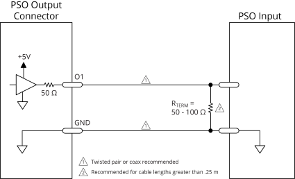
A PSO firing event can be triggered from a feedback channel or from a software trigger. You can get quadrature signals from feedback channels and PSO firing event signals after a PSO firing event occurs. When the PSO generates pulses, minimum latency occurs between the trigger condition and the output.
Aerotech recommends that you use an RS-422 line receiver or an opto-isolator if your system:
- Uses cables with long lengths in work areas where a lot of electrical noise occurs.
- Uses high-frequency pulse transmission.
For best performance, put the RS-422 line receiver or the opto-isolator near the electronics that receive the PSO output pulse.
Table 2-7: PSO Connector A Pinout
|
Pin # |
Label |
Description |
In/Out/Bi |
Connector |
|---|---|---|---|---|
| 1 |
O1+ |
PSO Output |
Output |

|
| 2 |
O1- |
PSO Output |
Output |
|
| 3 |
O2+ |
Reserved | N/A | |
| 4 |
O2- |
Reserved | N/A | |
| 5 |
O3+ |
Reserved | N/A | |
| 6 |
O3- |
Reserved | N/A | |
| 7 |
GND |
Ground |
N/A |
Table 2-8: PSO Connector B Pinout
|
Pin # |
Label |
Description |
In/Out/Bi |
Connector |
|---|---|---|---|---|
| 1 |
O1 |
PSO Output (5V TTL) |
Output |

|
| 2 | GND | Ground | N/A | |
| 3 |
O2 |
Reserved |
N/A | |
| 4 | GND | Ground | N/A | |
| 5 |
O3 |
Reserved |
N/A | |
| 6 |
GND |
Ground | N/A | |
| 7 |
+5V |
5 Volt Power Supply (500 mA) |
Output |
Table 2-9: Mating Connector Part Numbers for the PSO Connectors
| Specification | Description | |
|---|---|---|
| Type | 7-Pin Terminal Block | |
| Part Numbers | Aerotech: ECK02403 | |
| Phoenix: 1908114 | ||
|
Conductor Cross Section |
Solid or stranded | 20...26 AWG (0.14...0.5 mm2) |
| Stranded, with ferrule, without plastic sleeve | 20...24 AWG (0.25...0.5 mm2) | |
| Conductor Insulation Strip Length | 8 mm (5/16 in) | |
|
(1) Refer to the manufacturer website for additional information. |
||
Table 2-10: PSO Specifications
|
Specification |
Value |
|
|---|---|---|
|
Maximum PSO Output (Fire) Frequency |
TTL |
12.5 MHz |
|
Isolated |
5 MHz |
|
|
Output Latency [Fire event to output change] |
TTL |
60 ns |
|
Isolated |
160 ns |
|
|
1. Signals in excess of this rate will cause a loss of PSO accuracy |
||
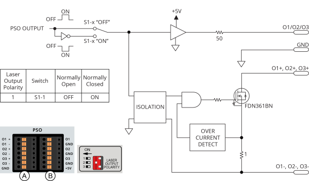
Figure 2-6: Current Sinking Configuration with Isolation

Figure 2-7: Current Sinking Configuration without Isolation

Figure 2-8: Current Sourcing Configuration with Isolation

Figure 2-9: Current Sourcing Configuration without Isolation