Encoder Output Connector
The Encoder Output interface echos the encoder signals out of the axis. Refer to the Drive Encoder Output functions in Automation1 Help.
Table 2-11: Encoder Output Connector Pinout
|
Pin |
Description |
In/Out/Bi |
Connector |
|---|---|---|---|
|
1 |
SIN- | Output |
|
|
2 |
Reserved | N/A | |
|
3 |
COS- | Output | |
|
4 |
Reserved | N/A | |
|
5 |
Reserved | N/A | |
|
6 |
Reserved | N/A | |
|
7 |
PSO External Sync | Input | |
|
8 |
+5V (500 mA max) | Output | |
|
9 |
SIN+ | Output | |
|
10 |
Reserved | N/A | |
|
11 |
COS+ | Output | |
|
12 |
Reserved | N/A | |
|
13 |
Reserved | N/A | |
|
14 |
Reserved | N/A | |
|
15 |
Ground | N/A |
Table 2-12: Mating Connector Part Numbers for the Encoder Output Connector
| Specification | 15-Pin Solder Cup |
Backshell |
|---|---|---|
| Aerotech Part Number |
ECK00100 |
ECK01022 |
| Amphenol Part Number (1) | DA15P064TXLF | 17E-1725-2 |
| Maximum Wire Size | 20 AWG (0.5 mm2) |
N/A |
|
(1) Refer to the manufacturer website for additional information. |
||
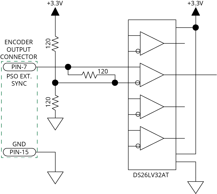
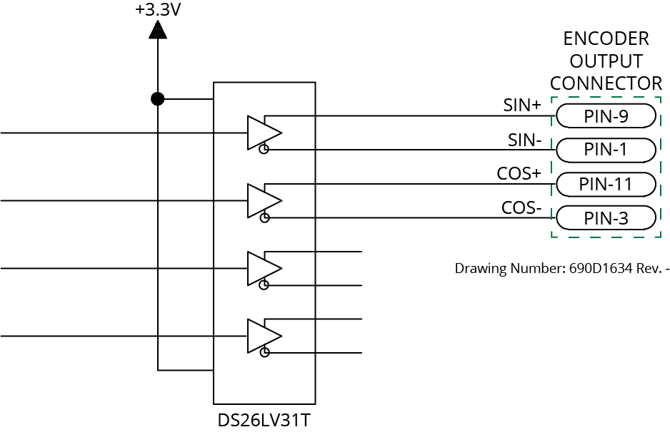
Figure 2-11: Encoder Outputs Schematic
You can use the external PSO synchronization functions to synchronize waveform generation with an external synchronization signal. When you activate this feature, the PSO Waveform module will not generate the configured waveform when an output event is received until the rising edge of the synchronization signal occurs. Refer to the PSO Waveform Functions in Automation1 Help.
Table 2-13: PSO External Sync Specifications
|
Specification |
Value |
|---|---|
|
Voltage |
3.3 VDC |
|
Frequency |
25 MHz Maximum |
|
On Time |
20 ns Minimum |
Figure 2-12: PSO External Sync Input Schematic