End of Travel Limits
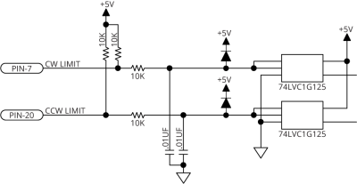
End of Travel (EOT) limits are required to define the end of the physical travel on linear axes. Positive or clockwise motion is stopped by the clockwise (CW) end of travel limit input. Negative or counterclockwise motion is stopped by the counterclockwise (CCW) end of travel limit input. All of the end-of-travel limit inputs accept 0-24 VDC level signals. Limit directions are relative to the encoder polarity in the diagnostics display (refer to End of Travel and Home Limit Input Diagnostic Display).
Table 2-8: End of Travel Limit Pins on the Axis Connector
|
Pin # |
Description |
In/Out/Bi |
|---|---|---|
|
3 |
Signal Common |
Output |
|
7 |
Clockwise End of Travel Limit |
Input |
|
8 |
+5 V Supply (500 mA) |
Output |
|
20 |
Counterclockwise End of Travel Limit |
Input |
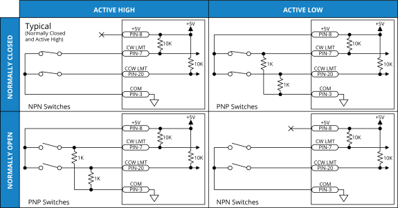
The active state (High/Low) of the EOT limits is software selectable (by the EndOfTravelLimitSetup parameter). End of Travel Limit Input Connections shows the possible wiring configurations for normally-open and normally-closed switches and the parameter setting to use for each configuration. Use NPN-type normally-closed limit switches (Active High) to provide fail-safe behavior in the event of an open circuit.
Figure 2-4: End of Travel Limit Input Connections