Encoder Phasing
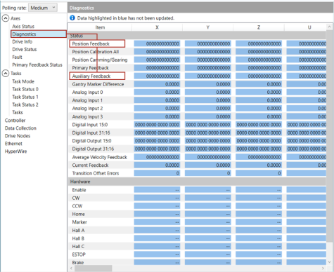
Incorrect encoder polarity will cause the system to fault when enabled or when a move command is issued. Encoder Phasing Reference Diagram (Standard) illustrates the proper encoder phasing for clockwise motor rotation (or positive forcer movement for linear motors). To verify, move the motor by hand in the CW (positive) direction while observing the position of the encoder in the diagnostics display (see Position Feedback in the Diagnostic Display).
Figure 2-11: Encoder Phasing Reference Diagram (Standard)
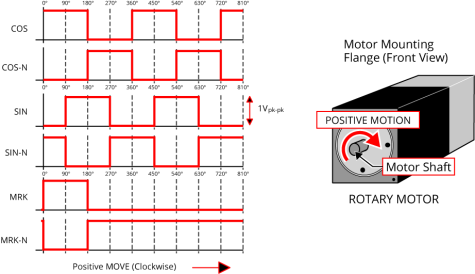
IMPORTANT: Encoder manufacturers may refer to the encoder signals as A, B, and Z. The proper phase relationship between signals is shown in Encoder Phasing Reference Diagram (Standard).
Figure 2-12: Position Feedback in the Diagnostic Display