HyperWire™ Card
The HyperWire bus is the high-speed communications connection to the HyperWire Card operating at 2 gigabits per second. The PC sends all command and configuration information through the HyperWire bus.
The driver for the HyperWire™ card is installed with the software. You can install the software before or after you install the HyperWire card. To install a HyperWire card, use the procedure in Installation.
Automation1 Software and Automation1 Drives
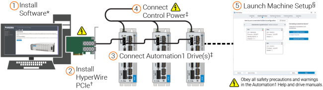
* Refer to the Automation1 Help system: Get Started / Software Setup / Install the Software.
† Refer to the Automation1 Help system: Get Started / HyperWire Communication / Install the HyperWire Card.
‡ Refer to the hardware manual for your drive.
§ Launch the Automation1 Studio application to access Machine Setup. Use this tool to load drive firmware.
If you want to operate without a HyperWire card:
- Open Automation1 Studio, select Machine Setup and click Start.
- Select "Yes" if you are prompted by any dialogs to proceed.
- During the Controller step of Machine Setup, select "Use Virtual Communication" or "Select Virtual". The option you see depends on if you have previously set up Machine Setup.
- Click "Save Progress And Close" to save the setting.
A3200 Software with Automation1 Drives
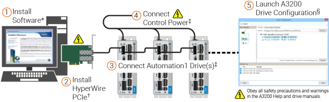
* Refer to Install the Software in the Getting Started section in the A3200 Help.
† Refer to Install the FireWire or HyperWire card in the Get Started section in the A3200 Help.
‡ Refer to the hardware manual for your drive.
§ Launch the A3200 Configuration Manager to access the Drive Configuration tool.
If you want to operate without a HyperWire card, refer to the Operation without a FireWire or HyperWire Card section of FireWire or HyperWire Card Options in the Help file.
IMPORTANT: All specifications and illustrations are for reference only and were complete and accurate as of the release of this manual. To find the newest information about this product, refer to www.aerotech.com.
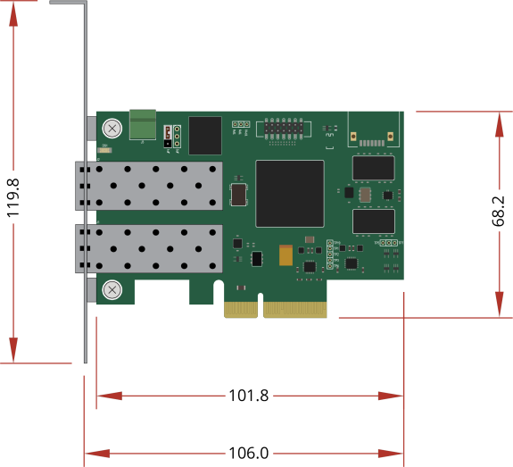
Figure 1-1: HyperWire Card Dimensions
Installation
IMPORTANT: Do not install the HyperWire card in a PCI Express (PCIE) expansion chassis. You must install the card in a PCIE slot, x4 or larger, on the motherboard.
DANGER: Risk of Electric Shock. Turn off the power and disconnect the power cord before you open the PC chassis.
To Install the HyperWire™ Card
- Power off the computer and disconnect the computer from the power supply.
- To get access to the motherboard, remove the computer system cover.
- Find an available PCIe slot, x4 or larger. If necessary, refer to your computer manual for information about available slots.
- Remove the cover of the available slot that you want to use.
- Carefully push the HyperWire card into the slot.
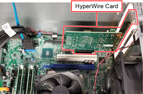
Figure 1-2: Open PCIE Slot
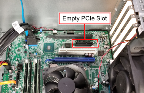
Figure 1-3: HyperWire Card Installed
- Attach the metal tab on the card to your computer with the method in your computer manual. This is typically a mounting screw.
- Put the cover on the computer.
- Connect the computer to the power supply and power on the computer.
HyperWire Card Firmware
Two firmware images are embedded on the HyperWire card, a Default image and a Recovery image. The default image is updated each time you update the firmware. The recovery image is the image of the original firmware that was installed at the factory. The position of the JP1 jumper determines the active firmware image on the HyperWire card (JP1 Jumper Positions). JP1 should remain in the default [1-2] position under most circumstances. The recovery mode should only be used if you think that the default firmware image has become corrupt.
Table 1-1: JP1 Jumper Positions
|
Image |
Position |
Description |
|---|---|---|
|
Default |
1-2 |
Firmware updates will overwrite this image. |
|
Recovery |
2-3 |
Use this image to reload the default image. The default image could become corrupt if, for example, power is interrupted during a firmware update. |
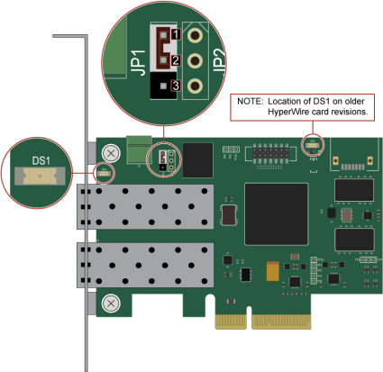
If you suspect that the default image has become corrupt, use the status LED DS1 on the HyperWire card (Default Position of JP1) to determine if the HyperWire card is initialized. The LED should come on and remain illuminated immediately after you turn on the PC. The LED can also flash briefly during a PC restart. If the LED continues to flash or remains off, the default firmware image could be corrupt.
Figure 1-4: Default Position of JP1
How to Restore Corrupt HyperWire Card Firmware:
DANGER: Risk of Electric Shock. Turn off the power and disconnect the power cord before you open the PC chassis.
- Turn off the power to the computer and disconnect the power cord.
- Disconnect the HyperWire cable from PC and the drive.
- Set JP1 on the HyperWire card to the Recovery [2-3] position to configure the card to use the Recovery firmware image. Refer to Default Position of JP1 for JP1 location and pin numbers.
- Uninstall the HyperWire card from its motherboard PCIe slot to access the jumper JP1, if necessary.
- Reinstall the HyperWire card after you have configured JP1.
- Reconnect the power cord and restart the PC.
- Make sure that DS1 is fully illuminated. Refer to Default Position of JP1 for DS1 LED location.
- The LED can be viewed through the bracket on the back of the PC.
- For an older revision of the HyperWire board, remove the PC cover to view the DS1 LED.
- If DS1 fails to illuminate correctly, the HyperWire card could be defective.
- Use the Drive Configuration dialog in the Configuration Manager to load firmware on to the HyperWire card.
- Turn the power off to the computer and disconnect the power cord.
- Set JP1 on the HyperWire card to the Default [1-2] position to configure the card to use the restored Default firmware image.
- Reconnect the power cord and restart the PC.
- Make sure that DS1 is fully illuminated.
- If DS1 fails to illuminate correctly, the HyperWire card could be defective.
- Reconnect the HyperWire cable and determine whether there is HyperWire communication between the PC and the drive.
- A HyperWire card configured in Recovery [2-3] mode might not establish HyperWire communication between the PC and the drive.
- If there is no communication, make certain the JP1 is set to [1-2]
Cables
The cables are SFP+ active optical cables. The are designed for use in 10-Gigabit Ethernet links.
Table 1-2: HyperWire Cable Part Numbers
|
Part Number |
Description |
|---|---|
|
HYPERWIRE-AO10-5 |
HyperWire cable, active optical, 0.5 m |
|
HYPERWIRE-AO10-10 |
HyperWire cable, active optical, 1.0 m |
|
HYPERWIRE-AO10-30 |
HyperWire cable, active optical, 3.0 m |
|
HYPERWIRE-AO10-50 |
HyperWire cable, active optical, 5.0 m |
|
HYPERWIRE-AO10-200 |
HyperWire cable, active optical, 20.0 m |
The connector module latches into the connector housing. Release the latch by pulling on the plastic pull tab located near the connector module (Cable Pull Tab).
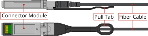
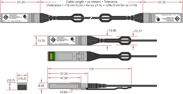
Table 1-3: Cable Specifications
Environmental Specifications
Table 1-4: HyperWire Card Environmental Specifications
|
Operating: 0° to 40°C |
|
|
Storage: -30° to 85°C |
|
|
Non-condensing |
The maximum relative humidity is 80% for temperatures that are less than 31°C and decreases linearly to 50% relative humidity at 40°C. |
|
0 m to 2,000 m above sea level. If you must operate this product above 2,000 m or below sea level, contact Aerotech, Inc. |
|
|
Pollution Degree 2 Typically only nonconductive pollution occurs. |
|
|
Use only indoors |
Table 1-5: HyperWire Cable Environmental Specifications
|
Ambient Temperature |
Operating: 0° to 70°C |
|
Storage: -20° to 75°C |
|
|
Humidity |
The maximum relative humidity is 85%. |