Encoder Input Connectors
The GL4 has two auxiliary encoder channels. Each encoder interface accepts an RS-422 differential line driver. Use the auxiliary encoder input channels with the Infinite Field of View (IFOV) and the "Marking on the Fly" functionality of the drive. You cannot use the auxiliary encoder input channels to close the position loop.
Table 2-33: Encoder Input Specifications
|
Specification |
Value |
|---|---|
| Encoder Frequency | 10 MHz maximum (25 ns minimum edge separation) |
| x4 Quadrature Decoding | 40 million counts/sec |
Table 2-34: Axis 1 Encoder Input Pinout (Encoder Input Connector A)
|
Pin |
Label |
Description |
In/Out/Bi |
Connector |
|---|---|---|---|---|
| 1 |
SIN1+ |
Encoder SIN+ Input |
Input |
|
| 2 |
SIN1- |
Encoder SIN- Input |
Input |
|
| 3 |
COS1+ |
Encoder COS+ Input |
Input |
|
| 4 |
COS1- |
Encoder COS- Input |
Input |
|
| 5 |
ESTOP+ |
Emergency Stop Digital Input + |
Input |
|
| 6 |
ESTOP- |
Emergency Stop Digital Input - |
Input |
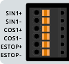
Table 2-35: Axis 2 Encoder Input Pinout (Encoder Input Connector B)
|
Pin |
Label |
Description |
In/Out/Bi |
Connector |
|---|---|---|---|---|
| 1 |
SIN2+ |
Encoder SIN+ Input |
Input |
|
| 2 |
SIN2- |
Encoder SIN- Input |
Input |
|
| 3 |
COS2+ |
Encoder COS+ Input |
Input |
|
| 4 |
COS2- |
Encoder COS- Input |
Input |
|
| 5 |
+5V |
+5V Encoder Power (500 mA max) |
Output |
|
| 6 |
GND |
Ground |
N/A |
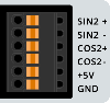
Table 2-36: Mating Connector Part Numbers for the Encoder Input Connectors
| Specification | Description | |
|---|---|---|
| Type | 6-Pin Terminal Block | |
| Part Numbers | Aerotech: ECK02405 | |
| Phoenix: 1704755 | ||
|
Conductor Cross Section |
Solid or stranded | 20...26 AWG (0.14...0.5 mm2) |
| Stranded, with ferrule, without plastic sleeve | 20...24 AWG (0.25...0.5 mm2) | |
| Conductor Insulation Strip Length | 8 mm (5/16 in) | |
|
(1) Refer to the manufacturer website for additional information. |
||
Table 2-37: GL4 to Drive Cable Part Numbers
|
Drive Type |
Cable P/N |
|---|---|
| XR3 | C26263-xx |
| XC2/XC2e | C25483-xx |
| Sync-Supported Drives (for example: XC4, XC4e) | Refer to Sync Port |
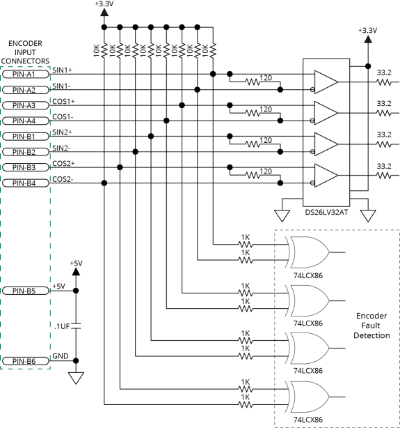
Figure 2-23: Encoder Input Connections Schematic