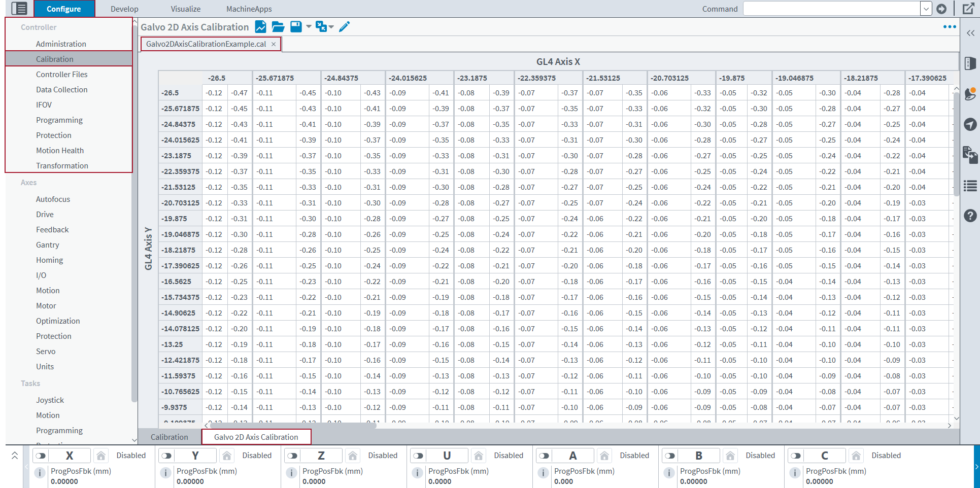
Galvo 2D Axis Calibration Module
Use the Galvo 2D Axis Calibration module to create, open, edit, and merge Galvo 2D Axis Calibration files that you can use with an Aerotech controller.
Table: Galvo 2D Axis Calibration Toolbar
| Name | Type | Description |
|---|---|---|
|
New File (Ctrl+N) |
Button |
Makes a new calibration file. |
|
Open File (Ctrl+O) |
Button |
Opens a calibration ( |
|
Save File |
Button |
Save ( This button also saves the changes that you make to an existing calibration table in the configured Galvo 2D Axis Calibration. The calibration table must be open in the Galvo 2D Axis Calibration module, and its tab must be selected. |
|
Button |
Save As… ( |
|
|
Button |
Save to Configured Calibration: Saves the calibration table from the open calibration file to the configured Galvo 2D Axis Calibration file. |
|
|
Button |
Save to File...: Saves a new file to the MDK File System, which contains the selected calibration from the configured Galvo 2D Axis Calibration file. You can save it as a calibration ( |
|
|
Merge File |
Button |
Merge: Merges a file into the selected file. For more information about how to merge two files, see Merge Calibration Files. |
|
Button |
Merge with Configured Calibration: Merges axis calibration from the configured Galvo 2D Axis Calibration file into the selected file. This button is available only if the configured Galvo 2D Axis Calibration file contains a calibration table for the same axes as those corrected by the calibration file that is currently open. |
|
|
Edit File Properties |
Button |
Opens a dialog that lets you edit the properties of the selected file. |
|
Menu |
Button |
You can find more settings for the Galvo 2D Axis Calibration module. To do this, select the Menu ( |
Galvo Calibration Files
In the Galvo 2D Axis Calibration module, your Galvo 2D axis calibration files must be associated with galvo scanner axes. You cannot create a calibration file if you do not have configured galvo axes. If your galvo is not configured, see Machine Setup to configure your galvo axes.
GL4 Scanner Calibration Files
Use the Galvo 2D Axis Calibration module to create and save calibration files in either the .cal or .csv file format. A GL4 calibration file in the .cal format can have a maximum of 138,000 points. The number of samples per axis must be odd and range from 3 to 32,769. The positions and corrections are stored in counts, primary units, or secondary units. The field of view can be any size.
Create a File
- In the Configure workspace, find the Controller category. Then select the Calibration topic.
- At the bottom of the topic, select the Galvo 2D Axis Calibration tab.
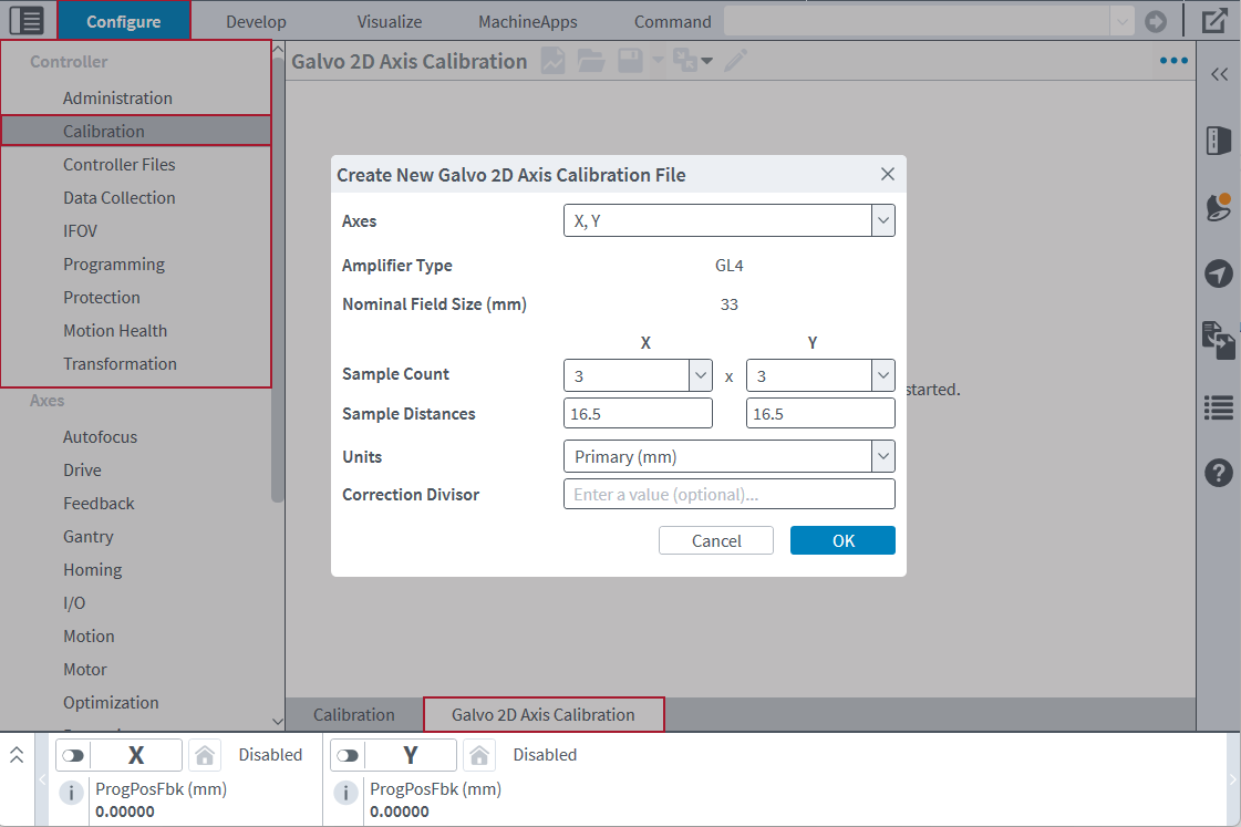
- On the toolbar, click the New File button. The Create New Galvo 2D Axis Calibration File dialog comes into view.
- Select the axes of the GL4 scanner for which you want to create a calibration file. The Amplifier Type and Nominal Field Size (mm) come into view.
- Select the number of samples per axis of the calibration table. The number of samples per axis determines the sample distances. The total number of correction values cannot be more than 138,000.
- Enter the Sample Distances for each axis of the calibration table that you want. These values are the distances between each correction position for the axes. This value is specified in units. These distances are automatically calculated if you use primary units that are linear.
- Select the Units you want to use for the sample distances and corrections.
- (Optional) Enter a value in the Correction Divisor value box. The correction divisor changes correction values from units to units / divisor.
- Click OK to close the dialog.
Use a .CSV File Format for the GL4 Calibration File
If you want to use a .csv file as a GL4 calibration file, the .csv file must obey these guidelines:
-
The number of rows and columns must be odd.
-
The total number of correction values cannot be more than 138,000.
-
Each row must have the same number of entries.
-
Each correction vector must be in the format that follows.
-
"Channel 1 Correction Value, Channel 2 Correction Value, Channel 3 Correction Value"
-
-
Each subsequent entry must be separated by commas and the entire entry must be inside double quotation marks (""). This is an example of a row from a three-column
.csvfile:-
"-3,1,0","-2,0,0","-3,-1,0"
-
-
The third channel in the
.csvfile is necessary, but when you import a.csvfile as a.calfile, this channel is ignored. -
The columns and rows must be evenly distributed over the field of view.
GI4 Scanner Calibration Files
Use the Galvo 2D Axis Calibration module to create and save calibration files in either the .cal or .csv file format. A GI4 calibration file in the .cal file format is always 65 x 65 entries. When you save a file that has other dimensions, the table automatically scales to 65 x 65 entries. The field of view is stored in counts, and the file shows a range of -32768 to 32767 (when 16-bit scanner resolution is used) or -524288 to 524287 (when 20-bit scanner resolution is used).
Create a File
- In the Configure workspace, find the Controller category. Then select the Calibration topic.
- At the bottom of the topic, select the Galvo 2D Axis Calibration tab.
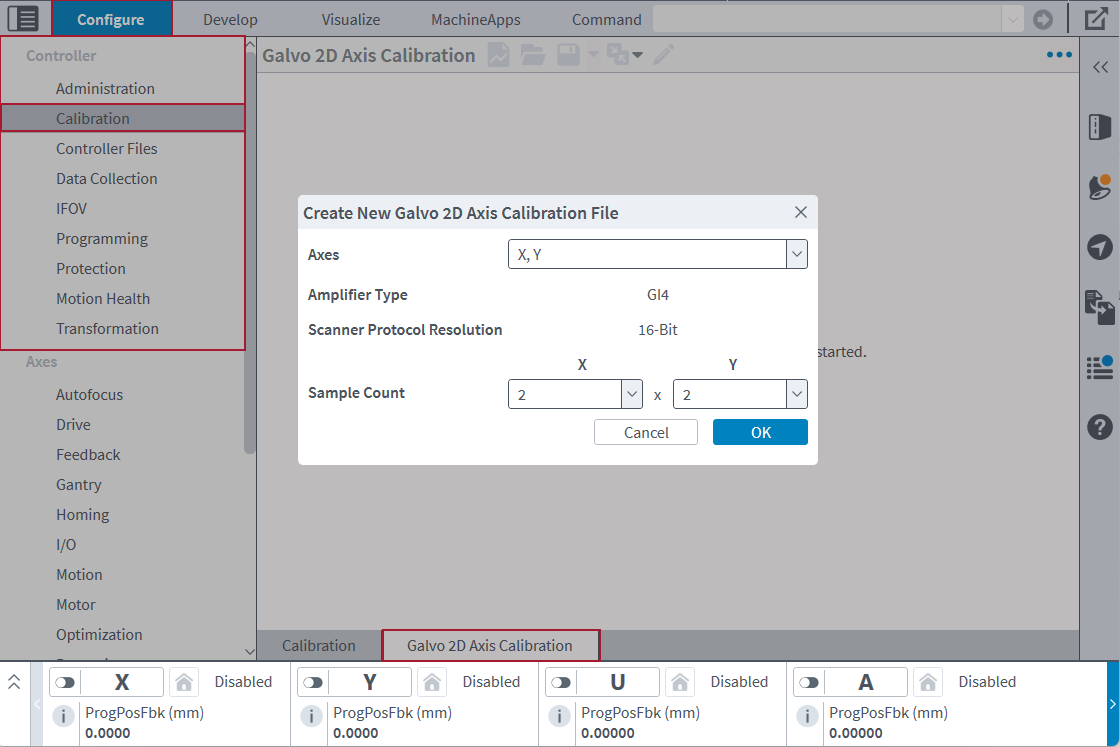
- On the toolbar, click the New File button. The Create New Galvo 2D Axis Calibration File dialog comes into view.
- Select the axes of the GI4 scanner for which you want to create a calibration file. The Amplifier Type and Scanner Protocol Resolution come into view.
- Select the number of samples per axis of the calibration table.
- Click OK to close the dialog.
Use a .CSV File Format for the GI4 Calibration File
If you want to use a .csv file as a GI4 calibration file, the .csv file must obey these guidelines:
-
Each row must have the same number of entries.
-
Each correction vector must be in the format that follows:
-
"Channel 1 Correction Value, Channel 2 Correction Value, Channel 3 Correction Value"
-
-
Each subsequent entry must be separated by commas, and all of the entries must be inside double quotation marks (""). This is an example of a row from a three-column
.csvfile:-
"-3,1,0","-2,0,0","-3,-1,0"
-
-
The third channel in the .
csvfile is necessary, but when you import a.csvfile as a.calfile, this channel is ignored. -
The columns and rows must be evenly distributed over the field of view.
-
The field of view is determined by the scanner protocol resolution:
-
In a file with 16-bit scanner protocol resolution, the first entry corresponds to the point (-32768, -32768). The last entry corresponds to the point (32767, 32767). Each intermediate entry evenly divides this range.
-
In a file with 20-bit scanner protocol resolution, the first entry corresponds to the point (-524288, -524288). The last entry corresponds to the point (524287, 524287). Each intermediate entry evenly divides this range.
-
In the
.csvfile, as you read the rows from top to bottom, the entries correspond to an increase in the Axis 2 position. As you read the columns from left to right, the entries correspond to an increase in the Axis 1 position.
-
Interpolation
When you scale a galvo calibration file, the application uses bicubic interpolation to calculate the new correction values. In general, bicubic interpolation makes accurate corrections for the galvo lens.
Change Precision in Calibration Files
To adjust the number of decimal places of precision in your calibration files, use the Precision settings. To do this, select the Menu ( ) button and click Settings. In the Settings dialog, make sure the Galvo 2D Axis Calibration tab is selected.
Display Precision
Display Precision is the number of decimal places that the application shows for a correction value. You can specify a value from 0 to 15. If you decrease the display precision, the application shows the values rounded to fewer decimal places. Display precision only changes how the application shows the value. It does not have an effect on the precision of the values in your calibration file.
Output Precision
Output Precision is the number of decimal places that the application applies to a correction value when you save the calibration file.
To have access to edit the Output Precision box, you must enable the Use output precision when saving files toggle. When you save the calibration file, correction values that have more decimal places than the specified output precision value are rounded. Correction values with fewer decimal places than the specified value are zero-padded.
If the Use output precision when saving files toggle is off, when you save the calibration file, the correction values are written to the file with as many or as few decimal places as are necessary for the full correction value.
IMPORTANT: If you use fixed precision when you save a calibration file, the correction values can lose precision. You will overwrite the original full-precision correction values with the rounded correction values.
Merge Calibration Files
You can merge two calibration files to get one calibration file with the corrections from both files. Typically, you merge files to improve calibration by merging measured corrections with the corrections that are active on the controller.
- Open one of the calibration files that you want to merge.
- Click the Open File button on the toolbar. The Open dialog comes into view.
- Select the file you want and click the Open button.
- Click the Merge File button on the toolbar. The Open dialog comes into view.
- Select the file you want to merge into the current file and click the Open button.
The corrections from the file that you selected are added to the corrections of the file that is currently open.
You can also merge a calibration file with the corrections that are active on the controller by using the Merge with Configured Calibration button.
- Open the calibration file that you want to merge.
- Click the Open File button on the toolbar. The Open dialog comes into view.
- Select the file you want and click the Open button.
- Click the Merge with Configured Calibration button on the toolbar. This button is available only if the configured Galvo 2D Axis Calibration file contains a calibration table for the same axes as those corrected by the calibration file that is currently open.
The corrections from the configured calibration table are added to the corrections of the file that is currently open. You can use the Save to Configured Calibration button to update the calibration that is active on the controller.
Rules for Merging Files
When you merge files, you must obey the rules that follow:
-
You cannot merge a file with itself.
-
Corrections in the open file that are outside of the field of view of the file you selected to merge do not change.
-
Corrections in the open file that do not align with corrections in the file you selected to merge are interpolated.
-
These rules apply to existing GL4 calibration files:
-
The file being merged cannot have a samples per axis dimension larger than 45,999.
-
The units of both files must be the same.
-
-
These rules apply to existing GI4 calibration files:
-
The file being merged must have dimensions of 65 x 65 entries.
-
The file being merged must have corrections in counts.
-
The file being merged must use the same scanner protocol resolution.
-


